Hardware Setup
In this section we are going to show in which connector you should attach each additional device.
Note: be cautios when disconnecting devices from DF13 connectors, the first times connectors could be stiff.
The image below, shows the most common hardware attached to Erle-Brain:
Typical Hardware Setup

PWM out
The Erle-Brain has 10 channel of PWM output. In this channels, the most typical devices that you could connect are: ESCs, servos, gimbal servos,...
The next image show which are the PWM channels:

The top row provides the PWM signal, the center 5v and the bottom is the GND signal. Make sure you plug the device connector in the right way.

RC Input
The radio control receiver must be connected in the channel 14 rail, as shown below:

Buzzer
The buzzer must be connected into single two pins DF13 connector of ther Erle-Brain.

GPS + Compass
As default, the GPS must be connected to the port Serial. This port will power up the device. The I2C bus is used to connect the compass to Erle-Brain.

I2C bus
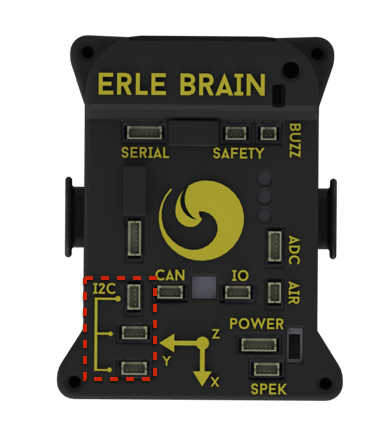
The Erle-Brain contains three I2C bus connectors, which gives access to the I2C1 bus. In this bus you could connect lots of different sensor and devices, i.e.: compass, gas sensors, temperature sensors, ...

Power
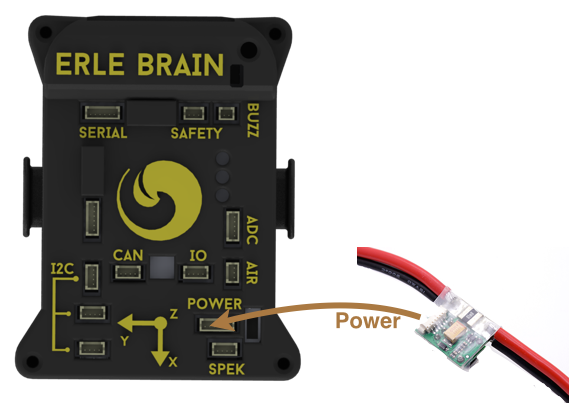
Use this connector to feed Erle-Brain from the Power-Module.

Other buses/ports

I/O
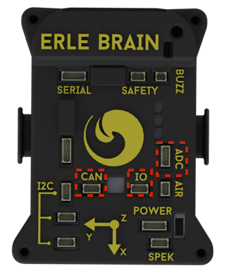
This connector allows to connect external hardware to two GPIOs. It also supplies with 3v3.
CAN
Use this connector to access Erle-Brain CAN bus.
Note: One good example of use of GPIO and CAN connectors are the ubleds.
ADC
Erle-Brain also has a dedicated ADC bus, that contains two ADC channels. The connector also supplies 5 volts.
Warning: The range of input of the ADCs are 0~1.8v. Do not connect any voltage that exceeds this voltage.
Discussion on some undocumented ports.