Current Measurement
The BeagleBone has a method under which the current consumption of the board, not counting the USB Host port and expansion boards, can be measured. The voltage drop across a .1 ohm resistor is measured to determine the current consumption.
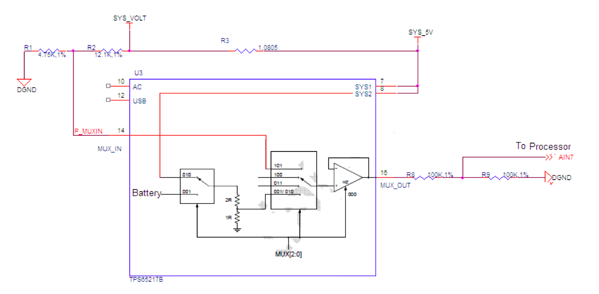
SYS_5V Connection
The SYS_5V rail is measured to determine the high side of the series resistor. The SYS_5V rail is connected to the MUX_OUT pin. Prior to being connected to the internal second multiplexer, the voltage is divided by 3. A 5V signal will result in a voltage of 1.66V at the MUX_OUT pin.
SYS_VOLT Connection
The SYS_VOLT rail is measured to determine the high side of the series resistor. The SYS_VOLT rail is connected to the MUX_OUT by setting the registers inside the TPS65217B. The resistors R2 and R1 are provided to keep the same voltage divider configuration as found in the SYS_5V rail located internal to the TPS65217B. However, a 5V rail will give you 1.41V as opposed to the 1.66V found internal to the TPS65217B. This works out to a divisor of 2.8. Be sure and work this into your final calculations.
MUX_OUT Connection
The MUX_OUT connection is divided by 2 before being connected to the processor. The reason for this is that if the battery voltage is connected, it has no voltage divider internally. If connected it could damage the processor. When calculating the voltages for either side of the resistors, that voltage is divided by 2. Be sure and include this in your calculations.
Current Calculation
The calculation for the current is based on .1mV is equal to 1mA. You can use the following formula to calculate the current using the voltage readings as read by the processor.
(((SYS_5V*2)*3.3)-((SYS_VOLT*2)*3.54)))/.1= Total (mA)